LED Watch

A wristwatch with no case and no screen: the face is 132 tiny white LEDs, charged by a solar cell, driven by one microcontroller. Board, power system, firmware and a working simulator, designed from scratch.

Status, 21 Oct 2026: revision A is designed, checked and quoted for assembly. It has not been ordered or built yet, so nothing has been powered up. Everything below is design work, simulation and review.
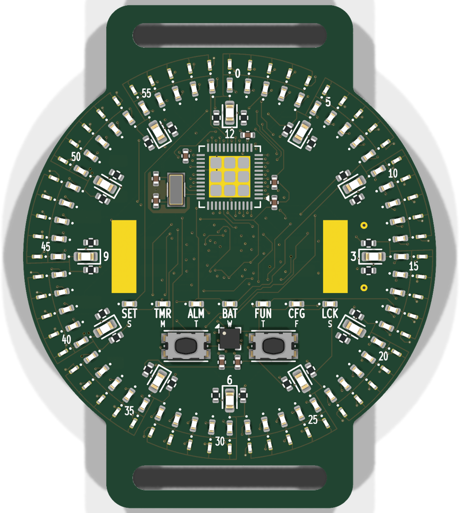
Front of the LED Watch circuit board: rings of tiny LEDs around a centre reserved for a solar cell

What it isOne board, front and back

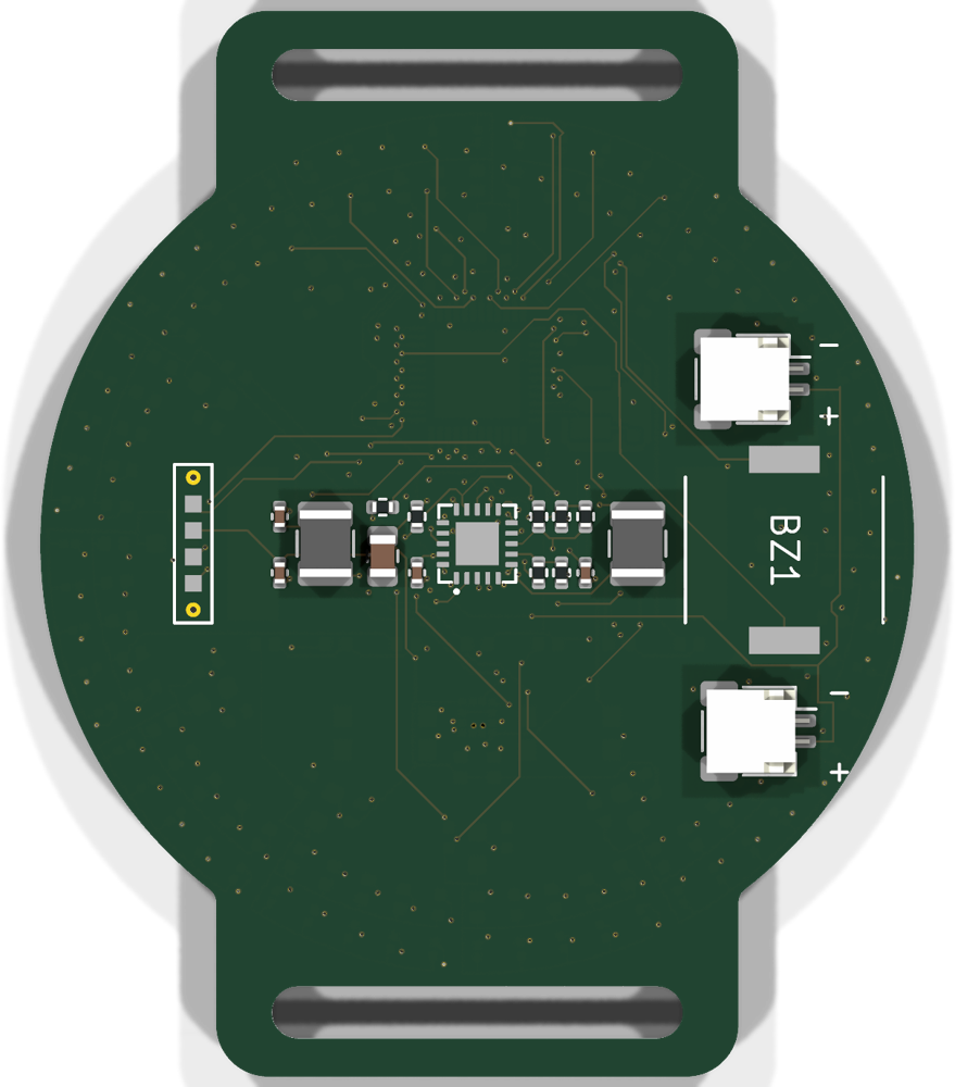
The LEDs and the solar cell are on the front. Everything else (microcontroller, power chip, battery plugs, buzzer) is on the back, so the watch is as thin as the parts allow.

Display

132 white LEDs on three rings: 12 for hours, 60 for minutes, 60 for seconds, each turned to its true angle on the dial. Seven more LEDs name the mode and double as weekday lights.

Brain

Microchip AVR128DB48 with a 32.768 kHz crystal. The 144-position LED grid is multiplexed straight from the chip's pins: no driver chips.

Power

A small solar cell feeds a TI BQ25570 energy harvester that charges two 70 mAh LiPo pouches. Sleep current target: a few microamps.

Senses

An ST LIS2DW12 accelerometer wakes the watch on a wrist raise or double tap (about 1 µA while waiting). A piezo buzzer rings the alarm.

Controls

Two buttons, low on the face. Modes: time, set, stopwatch, alarm, battery, settings, and a games menu with seven toys played on the LED rings.

Made by

42 mm round board, four layers, assembled by JLCPCB. Designed by Evan Finkle with Claude (Anthropic) doing research, scripting and layout automation.

The hardwareRevision A

Rendered from the actual KiCad board file that was sent for quoting. Two strap slots, a 42 mm circle, 197 parts.

Front side of the board
Front. Hour, minute and second LED rings; the two buttons; the mode LEDs (SET, TMR, ALM, BAT, FUN, CFG, LCK) with weekday letters; the accelerometer; the two gold pads where the solar cell sits.
Back side of the board
Back. The BQ25570 harvester and its two inductors, the two battery plugs (with + / - marks), the buzzer, and the four programming pads on the left edge (reset, battery, ground, UPDI).

Try itThe simulator

This runs the same logic as the watch's firmware, on the real LED positions and pin map taken from the board file. The watch starts asleep, like the real one: press LEFT or RIGHT, or the Raise wrist button, to wake it. Then click through the modes, tilt it, play the games. The status panel shows the LED current, the scan plan and the battery model.

Live simulator (the firmware logic, running in your browser)Open full screen ↗

Buttons

Z / ← left, X / → right. Hold left for one second to open mode selection from anywhere.

Motion

Drag the tilt pad, or use WASD. R raises the wrist, T double-taps, Space shakes.

Time and power

Speed the clock up to 600x, drain the battery, add sunlight, and watch how the brightness follows the battery voltage.

Development so farHow it got here

Sixteen days from a one-page brief to a board ready to order. The reasoning behind every decision is written down in the repository's decision log; this is the short version.

5 Oct

The brief, and a clock-face generator

White LEDs only, one individually placed LED per second, minute and hour, each turned to its true radial angle: 6 degrees apart on the minute and second rings, 30 degrees on the hour ring. A script places the rings from a few parameters, so the tightest layout that still routes can be found by search instead of by hand.

11–14 Oct

Simulator first, firmware second

The two-button interface (hold left to choose a mode, then left/right to move, wait to enter) was designed and built in the browser simulator before any hardware existed. The logic was then ported to portable C for the AVR and checked against the simulator frame for frame: 20 scenarios match exactly, with 71 unit checks and 197 hardware-layer checks passing. The AVR build is 31.7 KB of the chip's 128 KB flash.

12 Oct

A power system built from in-stock parts

A solar cell, a BQ25570 harvester and two small LiPo pouches. The harvester's three resistor ladders (battery overvoltage, battery-good, 3.3 V output) were recomputed from the datasheet equations and re-picked from values JLCPCB actually has in stock.

13–14 Oct

Hand placement, scripted routing

Evan placed the parts by hand in KiCad. Scripts then did the rest: a polar router for the LED rings, a grid router for the remainder, a ground plane, and pad-by-pad clean-up. The schematic is generated from a script and compared to the routed board connection by connection. First JLCPCB quote for five assembled boards: $308.63.

15 Oct

Cleaner copper

A pass that redrew traces in clean 45-degree moves cut the number of odd-angle pieces from 790 to 53, and moved traces out from under the microcontroller and the power chip.

18 Oct

The pre-order review found two things

Every pin of the harvester was checked against its datasheet. The 3.3 V divider was outside the datasheet's recommended range, so it was changed (output 3.309 V). Then the review of the battery plug found it was wired backwards compared with the battery maker's own wiring. Pin 1 had been battery-plus; theirs is ground. It was swapped on the board and schematic, and plus/minus marks were added to the silkscreen. This is exactly the kind of mistake that would have killed the first power-up.

19–21 Oct

Final checks

Board rule check: 0 errors, 0 unconnected nets. JLCPCB's manufacturability checker and its assembly checker (with the parts list and placement file loaded) flag only quirks of its part models, not copper problems. Final quote: about $312 for five assembled boards, plus shipping. Also written for the first power-up: a test plan that needs only a multimeter.

Facts and numbersThe details

Board42 mm round with two strap lugs, 4 layers, 1.6 mm; 0.10 mm tracks and spaces, 0.15 mm vias; black with gold finish
LEDs12 × 0603, 60 × 0402 and 60 × 0201 white LEDs on three rings; 7 × 0402 mode LEDs
Scan12 rows × 12 columns, one row at a time, about 3 LEDs lit at once; brightness follows the battery voltage
Harvestingcell open-circuit about 2.1 V in full sun; charge stops at 4.12 V; battery-good flag falls at 3.31 V
Sleeptarget 3–5 µA; the accelerometer waits at about 1 µA (5 µA with double-tap detection on)
Programmingfour pogo pads on the back (reset, battery, ground, UPDI); no connector parts
Parts list26 line items, all stocked by JLCPCB; the solar cell is soldered by hand

Honest statusWhat's done, what isn't

Done

  • Complete schematic and routed 4-layer board
  • Firmware core in C and a matching browser simulator
  • Review of the power design and every harvester pin
  • Quote and manufacturability checks for assembly
  • Bring-up test plan that needs no oscilloscope

Still open

  • The boards have not been ordered, built or powered
  • No firmware has run on a real chip yet
  • Solar charge rate is estimated, not measured
  • The accelerometer's land pattern is the stock one (the maker's note was unavailable)
  • A second pair of eyes on the power block, the crystal and the battery plugs

For reviewersRead more

Everything is public in one repository: the KiCad project, the scripts, the firmware, the simulator, and the decision log.